




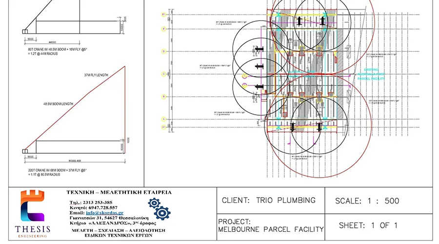
Load Lifting Studies (Lifting Plan)
Load lifting studies are a critical and integral part of any project involving the use of cranes or other lifting equipment for the transportation or placement of loads. These are technically documented studies that define how a lift should be performed safely, with technical precision and regulatory compliance, to protect personnel and equipment and ensure the successful completion of the task.The study must adhere to technical standards such as EN 13155, ISO 12480-1, and the Greek Government Gazette (FEK) 143/B/2003 regarding safety in lifting operations
Load lifting studies (Lifting Plans) are not merely formal documents or simple safety procedures. They are essential tools for technical design, prevention, and compliance, playing a decisive role in the success and safety of any project involving lifting loads with cranes or similar equipment.
The preparation of the study is not optional: in many cases, it is legally mandatory, while in others, it constitutes a specification set by the employer, supervising authority, or certification body.
Load Lifting Study Procedures
- Technical Characteristics of the Load
The study begins with a comprehensive technical description of the load: total weight, dimensions (length, width, height), shape, suspension points, and the center of gravity. If the load is eccentric or sensitive to torsion (e.g., a metal frame or equipment), this is explicitly stated. Accurate documentation of load characteristics is critical for equipment selection and process safety.
- Selection of Lifting Equipment
This step includes technical documentation for selecting the crane and auxiliary suspension means according to the load parameters and project requirements.
The analysis covers:
- Type of crane (e.g., telescopic, crawler, overhead crane)
- Reach, lifting height, boom length
- Load capacity charts, verification of permissible loads
- Selection of slings, chains, shackles, lifting beams, according to SWL/WLL (Safe Working Load / Working Load Limit)
- Calculation of sling angles and their effect on system strength
Equipment selection is based on manufacturer specifications and international standards such as EN 818 (lifting chains) and EN 1492 (slings).
- Analysis of the Site and Lifting Path
The exact layout of the equipment on site is recorded. A study is conducted of the lifting area and the complete path the load will follow from the suspension point to the final placement location.
Considerations include:
- Lifting radius and operating angle
- Height above ground or other levels
- Static and moving obstacles (buildings, networks, pipelines)
- Exclusion zone to prevent access by unauthorized personnel
- Space requirements for stabilization (outriggers), ensuring ground level stability
The study may include topographic mapping or drawings in plan and section views (e.g., AutoCAD).
- Ground and Support Base Inspection
Crane stability is of fundamental importance. An assessment is made of the distributed loads on each crane support (e.g., outriggers) and compared to the bearing capacity of the ground.
Where necessary, the use of:
- Load distribution steel plates
- Stabilization platforms
- Special foundations to minimize settlements
The study is based on standards such as ISO 4301-1 (Classification of cranes) and provides safety factors according to the ground category.
- Risk Analysis and Safety Measures
A qualitative and quantitative risk assessment is conducted related to the lifting operation, including:
- Load drop due to failure
- Equipment overturning
- Collision with obstacles or personnel
- Miscommunication within the team
- Access exclusion
- Defined routes and signaling
- Use of Personal Protective Equipment (PPE)
- Communication with a signaler (visual/auditory)
If required, an emergency action plan is included.
- Definition of Roles and Responsibilities
The study specifies the involved personnel and their responsibilities, according to ISO 12480-1 guidelines and occupational health and safety legislation.
Specifically:
- Appointed Person (Lift Supervisor)
- Crane Operator
- Rigger (Load Technician)
- Banksman / Signal Person
- Safety Technician or Supervisor (where required)
- Technical Drawings and Diagrams
Each study is accompanied by technical drawings depicting:
- Site plan showing crane position and load path
- Section views indicating heights, obstacles, and suspension points
- Diagrams of radius and operating angles
- Indications of exclusion zones and safety points
- Final Deliverables of the Study
The final lifting study includes:
- Complete technical report with calculations and explanations
- Technical memorandum referencing standards and justifying choices
- Supporting drawings
- Signature & stamp of the responsible Chartered Engineer
The study is delivered in printed or digital format (PDF) and forms part of the project’s technical safety documentation.
Environment, Energy & Security
- Energy Performance Certificate (EPC)
- Gas Tightness Certificate
- Environmental Studies
- Fire Protection Studies
- Health and Safety Officer
- Dangerous Goods Safety Advisor DGSΑ/ADR/RID/IMDG
- Responsible Declarations of the Electrician-Installer (Y.D.E. – DEH Plans)
- Technical Expert Assessment (Construction, Damages, Accidents)
- Loading Analysis and Planning for Heavy Construction Equipment
- Load Lifting Studies (Lifting Plan)